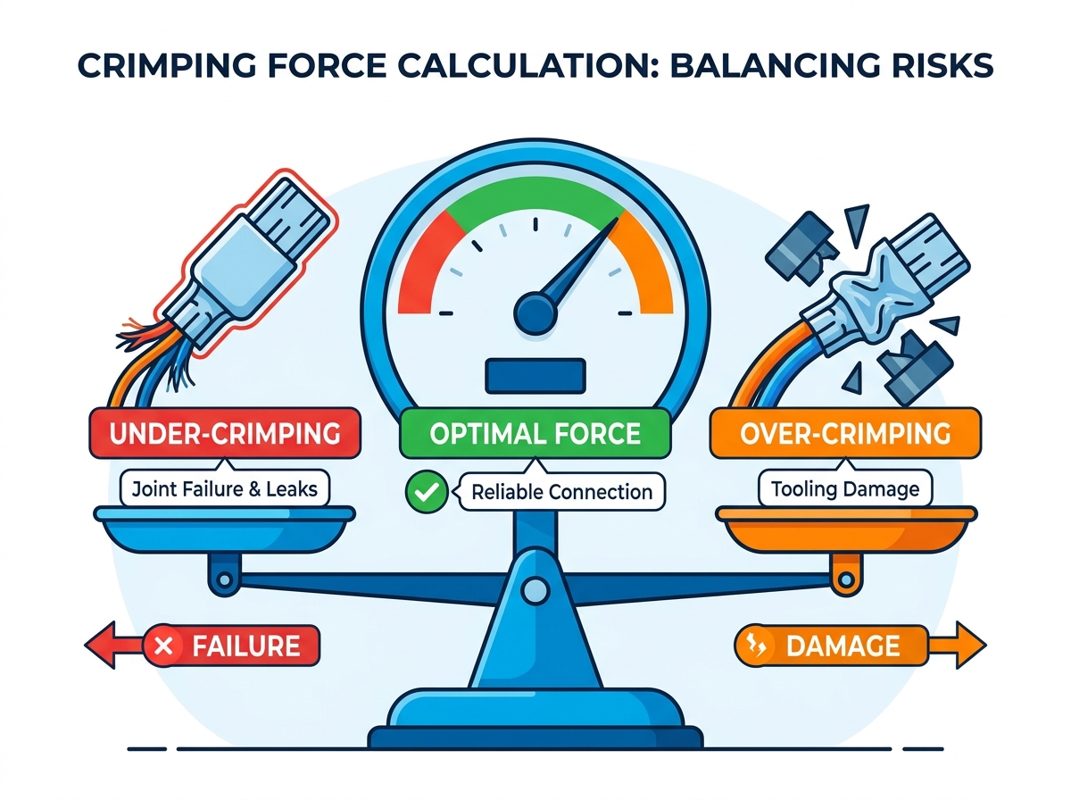
Inaccurate crimping force creates severe operational risks on the production floor. Under-crimping directly leads to catastrophic joint failure and dangerous electrical or fluid leaks. Conversely, over-crimping damages expensive tooling and significantly degrades terminal integrity. These extremes compromise safety and ruin production schedules.
Relying strictly on theoretical formulas causes major issues in manufacturing. You cannot make smart procurement decisions without accounting for material variance and specific machine capabilities. Theoretical baseline models often ignore real-world friction and dynamic equipment behaviors. Real-world applications demand a more nuanced approach than simple math provides.
This guide serves as a practical framework for purchasing managers and manufacturing engineers. We will help you evaluate equipment tonnage specs and understand key calculation variables. Ultimately, you will learn how to confidently shortlist the right crimping solutions for your facility.
Key Takeaways
Accurate crimping force calculation requires factoring in terminal material, yield strength, cross-sectional area, and tooling friction.
Procurement should build a 15–20% safety margin into their calculated tonnage to prevent machine fatigue during continuous high-volume production.
Theoretical calculations must always be validated empirically through pull-force testing and cross-sectional micrograph analysis.
Modern manufacturing demands dynamic Crimp Force Monitoring (CFM) integrated into the equipment, shifting the focus from static calculation to real-time quality assurance.
The Business Impact of Accurate Crimping Force Calculation
Required crimp force directly impacts product reliability and production scrap rates. When you apply the wrong force, your final assemblies fail in the field. Mastering your crimping force calculation prevents these critical failures and stabilizes your entire manufacturing process.
Risks of Under-specification
Under-specifying your press tonnage creates immediate bottlenecks. Your equipment will struggle to complete cycles cleanly. You will experience failed pull tests because the terminal never properly grips the conductor. As your product lines scale, underpowered machines lose their utility. They simply cannot handle harder alloys or larger gauge wires. You essentially lock your facility out of future growth opportunities by purchasing a weak machine today.
Consequences of Over-specification
Many engineers assume bigger is always better. This is a dangerous mindset. Overspecified machines bring significant downsides. Unnecessary high-tonnage hydraulic units consume massive amounts of floor space. They run at much slower cycle times compared to agile pneumatic systems. Furthermore, using a massive press on small, delicate applicators accelerates tool wear. You risk shattering precision dies because the machine delivers excessive force too quickly.
Compliance and Industry Standards
Proper force application ensures you meet strict industry standards. Modern manufacturers must adhere to frameworks like USCAR, IPC/WHMA-A-620, and DIN EN. These standards dictate acceptable compression ratios and pull-out thresholds. If your press fluctuates in force, your components will fail these mandatory compliance checks. Accurate calculations guarantee you hit the exact compression zone required by global quality authorities.
Core Variables in the Crimping Force Equation
Calculating the required tonnage is never a one-size-fits-all exercise. You must evaluate several interconnected variables. Each variable changes the total force required to achieve a gas-tight or leak-proof joint.
Material Hardness and Tensile Strength
Different terminal and fitting materials dramatically change your force multiplier. Brass yields relatively easily under pressure. Steel requires significantly more tonnage to deform properly. Copper alloys sit somewhere in the middle. You must also account for material work-hardening. As the press compresses the metal, the material actually becomes harder. This requires the machine to push even harder at the bottom of the stroke.
Cross-Sectional Area
You must evaluate the combined area of your materials. This includes the conductor or hose alongside the terminal barrel itself. A thicker barrel wall naturally demands more compressive force. Larger wire gauges exponentially increase the required tonnage. You cannot look at the wire size alone; the terminal geometry plays an equal role in the cross-sectional resistance.
Crimp Profile and Tooling Friction
The die geometry dictates how force transfers into the material. A standard B-crimp focuses force differently than a hex crimp. A 4-point indent profile concentrates extreme pressure into very small areas. Friction coefficients also alter your total required tonnage. Plated terminals might slide through the die smoother than raw, unplated metals. High friction robs your machine of effective crimping power.
Material Type
Typical Yield Strength Range
Friction Coefficient Impact
Application Profile
Standard Brass
Low to Medium
Moderate (improves with tin plating)
Automotive terminals, standard B-crimps
Copper Alloys
Medium
Low to Moderate
Heavy-duty electrical lugs, hex crimps
Stainless Steel
Very High
High (requires heavy lubrication)
Hydraulic fittings, 4-point indents
The Limitation of "Rule of Thumb" Calculators
Online calculators provide helpful baselines, but they never offer guarantees. We transparently warn buyers against trusting them blindly. Actual required force often deviates based on specific alloy batches. Even slight variations in plating thickness change how the terminal compresses. Use theoretical calculators to start your research, but never finalize a machine purchase without testing physical samples.
Translating Calculated Force into Equipment Tonnage Specifications
Once you understand your theoretical force requirements, you must translate them into a machine specification. Different driving mechanisms suit different force profiles.
Comparing Solution Categories
Pneumatic presses excel in low-force, high-speed environments. They actuate quickly but lack extreme brute strength. Electromechanical presses offer precise force profiling. They allow you to control the exact speed and pressure throughout the entire stroke. Hydraulic presses dominate the high-tonnage, heavy-duty category. They provide massive, sustained force ideal for thick steel hoses and large gauge battery cables.
The Safety Margin Rule
Buyers should never purchase a machine where their maximum calculated force equals the machine's peak rated tonnage. We highly recommend the 80% utilization rule. If your application requires 4 tons of force, do not buy a 4-ton machine. Purchase a 5-ton machine instead. This prevents machine fatigue during continuous high-volume production. Running a press constantly at its absolute maximum limit destroys internal seals and bearings.
Dynamic vs. Static Force
Force changes continuously throughout the stroke cycle. Peak force capability is only one part of equipment evaluation. A press might boast a high peak tonnage, but it might only deliver that force at the very bottom dead center of the stroke. Your application might require sustained force earlier in the compression cycle. Understanding dynamic force curves ensures the machine actually performs well for your specific terminal.
Crimp Force Monitoring (CFM) vs. Static Calculation
Modern production standards require more than just a good initial setup. You need continuous verification.
Scalability and Quality Control
Frame your initial calculation as the first step. Think of CFM as the ongoing verification. Static calculations get the machine running. CFM keeps the machine honest. As your production scales, manual quality checks become impossible. You need an automated system watching every single cycle.
How CFM Validates Calculations
Integrated monitors measure the force-over-time curve during every stroke. They compare the current cycle against a known good baseline. This dynamic curve detects tiny variations. It catches missing wire strands instantly. It detects if wire insulation accidentally slipped inside the crimp zone. It even alerts you to gradual tool wear before you start producing bad parts.
Evaluating CFM Capabilities
Not all monitoring software performs equally. When reviewing built-in monitoring systems, buyers should look for specific advanced features. A basic peak-force monitor is rarely enough for complex automotive or aerospace applications.
Drift Compensation: The software must adjust for natural temperature changes in the factory environment.
False-Reject Filtering: The system should distinguish between actual defects and harmless mechanical noise.
Traceability Data Logging: The machine must store force curves for historical quality audits and compliance tracking.
Buyer’s Checklist: Evaluating and Shortlisting Crimping Equipment
Purchasing the right equipment requires a systematic approach. Do not rely solely on a vendor's glossy brochure. Force them to prove their machine handles your specific requirements.
Validation Protocols
Require your vendors to perform physical sample processing. They must conduct capability studies (Cpk) using your actual wires and terminals. A theoretical match means nothing if the machine cannot achieve a Cpk of 1.33 or higher on your parts. This empirical data proves the equipment handles your calculated load consistently.
Tooling Compatibility
Assess whether your required force necessitates proprietary heavy-duty dies. Sometimes a standard applicator cannot handle the required load without flexing. Flexing destroys crimp geometry. Verify if the machine accepts industry-standard applicators or if it forces you into a proprietary tooling ecosystem. Flexibility in tooling often saves you from massive operational headaches later.
Next-Step Action
Compile a matrix of your toughest applications. Document your largest wire, your thickest hose, and your hardest terminal material. Submit this matrix to vendors for bespoke application engineering. Let the experts run the complex calculations on your absolute worst-case scenarios. This ensures any machine you shortlist handles your most demanding production days with ease.
Conclusion
Accurate crimping force calculation bridges the critical gap between mechanical engineering and smart equipment procurement. You cannot separate the physics of the crimp from the mechanics of the press. They rely entirely on one another.
We advise against treating equipment selection as a pure commodity purchase based on theoretical tonnage alone. A press is a dynamic manufacturing tool. Ignoring variables like material hardness, tooling friction, and safety margins will inevitably compromise your production lines.
Take action today to secure your production quality. We encourage you to contact our application engineering team for a customized force analysis and equipment recommendation based on your specific product drawings.
FAQ
Q: What is the standard formula for calculating needed crimp force?
A: The basic conceptual formula multiplies the cross-sectional area of the materials by the material tensile strength, then applies a specific crimp factor based on die geometry. However, theoretical formulas only provide a baseline. You must always validate these numbers through empirical testing and cross-sectional analysis.
Q: How much safety margin should I add to my crimp force calculation?
A: You should add a standard 15% to 20% buffer to your maximum calculated requirement. We recommend the 80% utilization rule. Running a machine constantly at its maximum rated tonnage accelerates wear on internal components. A proper safety margin ensures machine longevity and continuous reliability.
Q: Does crimping force change depending on the die type?
A: Yes, the die profile significantly alters the required force. A hex crimp distributes pressure differently than a standard B-crimp. Specialized profiles like 4-point indents concentrate extreme force into tiny surface areas. These geometric differences change the friction coefficients and alter the total tonnage required.
Q: Can a machine have too much crimping force?
A: Having extra machine capacity is fine, but applying too much force is dangerous. High-tonnage machines with poorly adjusted shut heights will crush components. Excessive force applied prematurely destroys delicate applicators and ruins terminal integrity. You must adjust the equipment precisely to match your application.
Handanshi Kangmai Hydraulic Equipment Co., Ltd. is located in the east of Wangzhuang,on the Hanlin expressway. Our main products have 9 series and 50 types which contains hose crimping machine, hose cutting machine,hose skiving machine...